
About
This blog post goes over my implementation of a ray traced audio system in C++ for my second year project at BUAS. Normally in games audio typically uses pre-baked reverb zones, echo zones and occlusion zones, which don't accurately respond to the dynamic environment. With ray traced audio you can get a more physically accurate approach by simulation sound rays through the environment using geometric acoustics. My system works by shooting rays from audio sources into the scene, reflecting off surfaces, transmitting through objects, and eventually reaching the listener. The data that is then collected, is used for the DSP (Digital Signal Processor) chain that applies different effects like occlusion, echoes and attenation. My goal was to create a ray traced audio system that automatically adepts to any environment without manual setup.
The audio file
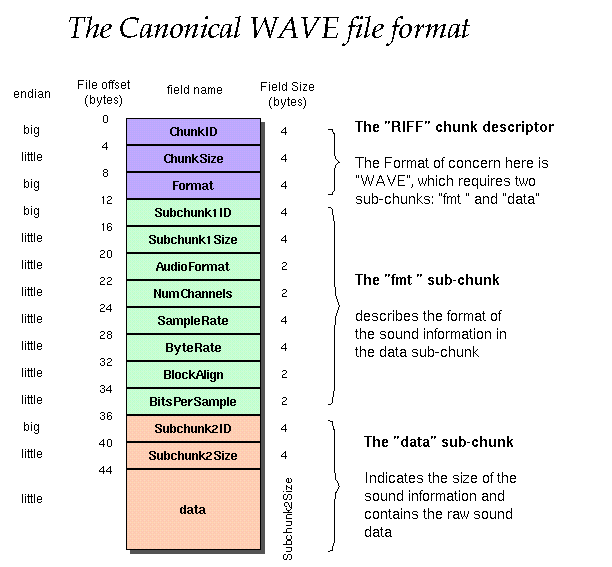
I will be using the WAV file format for this project. I am using this because WAV files store uncompressed PCM(Pulse Code Modulation) audio data. This makes it so its easy to read audio samples and apply DSP effects without the risk of losing quality. A WAV file consists of a header that describes the audio format, followed by the raw sample data. The header contains all kinds of information like sample rate, number of channels and bit depth.
std::ifstream wavfile(_filePath, std::ios::binary);

if (wavfile.is_open())
{
	// Read the WAV header
	char chunk_ID[4];              //  4  riff_mark[4];
	uint32_t chunk_size;           //  4  file_size;
	char format[4];                //  4  wave_str[4];

	char sub_chunk1_ID[4];         //  4  fmt_str[4];
	uint32_t sub_chunk1_size;      //  4  pcm_bit_num;
	uint16_t audio_format;         //  2  pcm_encode;
	uint16_t num_channels;         //  2  sound_channel;
	uint32_t sample_rate;          //  4  pcm_sample_freq;
	uint32_t byte_rate;            //  4  byte_freq;
	uint16_t block_align;          //  2  block_align;
	uint16_t bits_per_sample;      //  2  sample_bits;
	char sub_chunk2_ID[4];		   //  4  data_str[4];
	uint32_t sub_chunk2_size = 0;  //  4  sound_size;
We can then read the WAV file's chunk ID to check for the RIFF identifier to verify if its a valid WAV file, then read the format to check if its a WAVE format.
wavfile.read(chunk_ID, 4);

if (std::string(chunk_ID, 4) == "RIFF")
{
    wavfile.read(reinterpret_cast(&chunk_size), 4);
    wavfile.read(reinterpret_cast(&format), 4);

    if (std::string(format, 4) == "WAVE")
When having read through the whole file we can then use sub_chunk2_size to calculate the amount of samples. These samples are then stored in a vector for real-time processing in the audio engine. Once the audio is loaded these samples are fed to the DSP chain to apply audio effects to them.
std::vector audio_data(sub_chunk2_size / sizeof(int16_t));
wavfile.read(reinterpret_cast(audio_data.data()), sub_chunk2_size);
wavfile.close();  // Close audio file
Stereo Panning
To create the effect of directional sound in 3D space, I implemented stereo panning based on the audio sources position relative to the listener. The function calcualtes the angle between the listeners forward direction and the direction to the sound source. This maps it to a panning value between -1 (fully left) and 1 (fully right). The implementation uses the cross product of the listener's forward vector to get the right vector, then uses a dot product to determine how far the sound is on the left or right side of the listener. The pan value is then converted to individual channels using cosine and sine, this technique is called Equal power panning. This ensures that the loudness remains constant as sound moves from left to right, preventing that the center sounds quieter.
glm::vec3 dir = audiosourcePosition - listenerPosition;

glm::vec3 norDir = glm::normalize(dir);
glm::vec3 norRight = glm::normalize(glm::cross(listenerForward, glm::vec3(0, 1, 0)));

float pan = glm::dot(norDir, norRight);

float angle = (pan + 1.0f) * PI * 0.25;
_left = cosf(angle);
_right = sinf(angle);
Occlusion
To have more realistic audio I added occlusion to the DSP(Digital Signal Processor) chain. When sound travels through obstacles, high frequencies are absorbed more than low frequencies, this is why sounds are muffled through walls. To simulate this effect I implented an occlusion system that shoots a direct ray from sound source to the listener and applies a low pass filter when objects block the path. If the ray intersects with geometry, the ray gets the object's sound material, which contains an absorption coefficient (alpha). This value ranges from 0.0 (no absoption) to 1.0 (fully absorbed).
glm::vec3 dirToListener = listenerPosition - source.position;
SoundRay occlusionRay(source.position, dirToListener, 0.0f);
OcclusionTrace(occlusionRay, listenerPosition, audioManager->GetListener().listenerRadius);

if (hitGeometry)
{
	// Get material properties and set absorption
	int primIdx = tbRay.hit.prim;
	int objIDx = GetIDFromTriangleIdx(primIdx);

	for (auto& aMesh : audioManager->GetAudioMeshes())
	{
		if (objIDx == aMesh.meshTag.ID)
		{
			_sRay.alpha = aMesh.soundMaterial.absorpValue;
			break;
		}
	}

	return;
}

//Low pass filter formula
output = alpha × input + (1 - alpha) × previous_output
I am using a first-order IIR(Infinte Impulse Response) low pass filter, also known as a one pole filter. The filter works by blending the current sample and the previous sample. The alpha value controls how much smoothing is applied. Higher values let more high frequencies through, while lower values create a stronger muffling effect. The reason I chose for a IIR filter instead of a FIR filter is that a IIR filter is more efficient than a FIR filter. This is because it uses less coefficients. Normally the alpha is calculated based on the cutoff frequency but for my case it is a single value that the designer can define for each object when applying a sound material to the object. Some values that apply to different materials: Concrete ~0.3, wood ~0.5, fabric ~0.7.
Echo
Echoes occur when sound reflects off distant surfaces and returns to the listener after a delay. To add more realism I implemented the echo effect into my DSP chain using a feedback delay line using a circular buffer, where the delay time is calculated from the distance sound travels (at 343 m/s, the speed of sound in air at 20°C). The circular buffer stores previous audio samples, and by reading the samples with a delayed position, we create a echo effect.
	float delayInMS = (ray.totalDistance * 1000) / 343;

	int readIdx = audioSource.echoWritePos * 2;
	float leftEcho = audioSource.echoBuffer[readIdx];
	float rightEcho = audioSource.echoBuffer[readIdx + 1];
In the first part of the echo implementation, we read from the circular buffer at the current write position (multiplied by 2 for stereo interleaving) to get the echo from previous frames.
	float decay = 0.4f;
	float distance = glm::clamp(ray.totalDistance * 0.01f, 0.0f, 1.0f);
	float echoDecay = decay * (1.0f - distance * 0.3f);
The second part calculates the decay of the echo based on distance. I calculate a decay factor that reduces echo intensity based on how far the ray has traveled, with this longer ray paths make distant echoes quieter then near ones.
	_leftOut = (_leftDry * DRY_MIX) + (leftEcho * WET_MIX);
	_rightOut = (_rightDry * DRY_MIX) + (rightEcho * WET_MIX);

	audioSource.echoBuffer[readIdx] = _leftDry + (leftEcho * echoDecay);
	audioSource.echoBuffer[readIdx + 1] = _rightDry + (rightEcho * echoDecay);

	audioSource.echoWritePos = (audioSource.echoWritePos + 1) % audioSource.echoDelaySamples;
The third and last part is the feedback loop. The output mixes the dry (original) signal with the wet (echo) signal using blend factors. After that we write the dry signal plus the decayed echo back into the buffer. This creates the feedback loop that generates multiple echoes, each quieter than the last. The write position then moves circularly, overriding the oldest samples. I do this because its memory efficient and avoids needing to shift data around.
Ray tracing
For the ray tracing part I cast rays from each audio source to simulate how sound propagates through the environment.
Each frame, I shoot multiple rays in different directions using a Fibonacci sphere (more on that later), trace their paths
and as the bounch around the world and accumulate the energy and distance traveled by rays that reach the listener.
Fibonacci sphere:
To make sure the rays are all evenly distributed on a sphere I am using the Fibonacci sphere algorithm. This creates
a nearly uniform spherical distribution without clutering on the poles.
glm::vec3 CalculateFibonacciSphere(const int& _maxPoints, const int& _currentPoint, const float& _radius)
{
	float phi = (1.0f + std::sqrt(5.0f)) / 2.0f;//Calculating golden ratio

	float x = static_cast(_currentPoint) / phi;
	float y = static_cast(_currentPoint) / static_cast(_maxPoints);

	float theta = 2.0f * PI * x;
	float phiAngle = std::acos(1.0f - 2.0f * y);

	float sinPhi = std::sin(phiAngle);
	float cosPhy = std::cos(phiAngle);

	glm::vec3 pos(
		std::cos(theta) * sinPhi * _radius,
		std::sinf(theta) * sinPhi * _radius,
		cosPhy * _radius);

	glm::vec3 dir = glm::normalize(pos);

	return dir;
}
for (int i = 0; i < source.rayAmount; i++)
{
	SoundRay ray(source.position, CalculateFibonacciSphere(source.rayAmount, i, 1.0f), 0.0f);
	// ... tracing logic

	if (ray.reachedListener)
	{
		sRay.energy += ray.energy;
		sRay.totalDistance += ray.totalDistance;
	}
    for (SoundRay& transRay : transmittedRays)
    {
	std::vector nestedTrans;
	Trace(transRay, 0, listenerPosition, lr, nestedTrans, RayType::Transmitted);
	if (transRay.reachedListener)
	{
		if (!ray.reachedListener)
		{
			transAmount++;
			sRay.energy += transRay.energy;
		}
	sRay.totalDistance += transRay.totalDistance;
	}
    }
}
Transmission
With the rays, each ray when it hits an object will also create a new transmission ray with reduced energy. The reduction of the sound energy is like real life where when sound hits an object, a part of it goes through the object, part of it reflects, and a part of it gets absorbed. This ray goes through the object and continues tracing through the scene before potentially reaching the listener. The transmitted rays contribute to the total sound energy and distance if they reach the listener. This creates a more realistic experience when sound comes from behind a wall.
float invNumRays = 1.0f / source.rayAmount;
sRay.totalDistance *= invNumRays;
invNumRays = 1.0f / (source.rayAmount + transAmount);
sRay.energy *= invNumRays;
Eventually when the tracing is done the average of all the values are taken and supplied to a single ray that gets stored, so later it can be used to calculate the different sound effects in the DSP chain.
For the intersection of the rays with the environment I am using TinyBVH(make into link) by Jacco Bikker. This spatial acceleration structure organizes scene geometry into a tree, allowing ray intersections to be found in O(log n) time instead of checking every triangle. This gets me the data to calculate the intersection point of where the sound ray collides with an object. With the intersection point and the starting point I can then calculate a point on that line using GetNearestPointOnLineSegment function to check how far the listener is from the ray. This makes it possible for the listener to detect the sound rays.
// ... intersection logic

	//Calculate intersection point
	glm::vec3 prevIntersectionPoint = _sRay.origin;
	glm::vec3 intersectionPoint = _sRay.origin + _sRay.distance * _sRay.direction;

	//Calculate distance from point on ray line and player position
	glm::vec3 pointline = GetNearestPointOnLineSegment(_listenerPos, intersectionPoint, prevIntersectionPoint);

	float ilDis = glm::distance(pointline, _listenerPos);
	if (ilDis < _listenerRadius)//Check if ray has hit player
	{
		_sRay.reachedListener = true;
			if (_depth == 0)
				_sRay.hasDirectPath = true;
		return;
	}
When a ray intersects with geometry, it then finds the object's sound material to get its absorption value. If the ray can still go through object's a new transmitted ray is created, that will be shot through the object.
// ... getting object material logic

	if (_sRay.transmissionAmount > 0 && _sRay.energy > 0.005f)
	{
		SoundRay transmittedRay = CreateTransmissionSoundRay(_sRay, intersectionPoint, soundM);

	    if (transmittedRay.energy > 0.1f)
		transmittedRays.push_back(transmittedRay);
	}
The ray's energy gets reduced depending on the absorption value of the material. This means that if the absoption value is 0.2 20% of the rays energy gets absorbed by the surface and 80% reflects. The ray then calculates a reflection using a reflection formula: R = D - 2N(D·N), where D is the incident direction and N the normal of the triangle. After updating the rays origin and direction the Trace function is called again. With this you have a recursive behavior as long as the sound ray has enough energy.
_sRay.energy *= (1.0f - soundM.absorpValue);

	//Calculate reflection
	glm::vec3 reflection = _sRay.direction - 2.0f * normals[primIdx] * glm::dot(_sRay.direction, normals[primIdx]);

	_sRay.origin = intersectionPoint + reflection * EPSILON;
	_sRay.direction = reflection;

	Trace(_sRay, _depth + 1, _listenerPos, _listenerRadius, transmittedRays, _rt);
Conclusion
These are currently the features implemented into my ray traced audio tool. Although not everything is implemented yet, in the future I plan to add more features and also improve the performance and user friendliness to make it a proper tool that can be used in any project. I learned a lot from this project, mainly about how sound works and how it can be applied in programming, and I hope you also learned something about it. Thank you for reading my blog. PS. did you find the ducky :)
References
WAV File Info
Read WAV file
Feed back echo
Absorption values of different materials
TinyBVH by Jacco Bikker
Fibonacci sphere
My inspiration for ray traced audio